All news


FILIP JORISSEN UPDATES US ON MPC RESULTS AT INFRAX
Posted in: Blog-posts

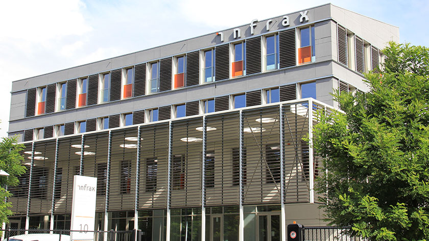
This post presents some preliminary simulation results of the Model Predictive Control (MPC) implementation of the Infrax office building. This building consists of four floors, each containing multiple zones that are simulated individually. The ventilation of is controlled individually per zone, while the concrete core activation is controlled individually per floor. The heat and cold production devices are also controlled by the MPC, but these are not discussed in detail here. The MPC is configured to minimize the electrical power use [kWh] while maintaining the zone temperatures between 22 and 24 degrees.

Figure 1: Zone Temperatures
The bottom of figure 1 shows the zone temperatures during a winter period, as illustrated by the sub-zero ambient temperatures at the top of the figure. The bottom subplot shows that the temperatures stay between the temperature constraints of 22 and 24 degrees. The third subplot shows that the four floors of the building have different heating requirements and therefore the two-way valve control signals are clearly different. Furthermore, incident solar irradiation and internal heat gains suffice to heat up the building on sunny days, which is illustrated by the CCA thermal power, which becomes zero during most days. However, at night the heating requirements rise significantly.

Figure 2: Ventilation System
The second figure focusses on the ventilation system. Each of the zone VAV control signals are indicated in the middle subplot. This shows that for most zones, the VAVs do not need to be opened fully to satisfy the CO2 concentration constraint of 1000 ppm. However, there exists one zone for which the VAV does open fully (indicated using a dashed blue line). Indeed, there exist two zones where the CO2 concentration limit is exceeded. The MPC increases the fan speed to its maximum speed in order to avoid the violation, as indicated by the maximum AHU pressure head of 180 Pa. This does not satisfy to keep the concentration below the upper limit but it does show that the MPC works correctly. Note that this violation is merely for illustrative purposes since the large simulated zone occupancy is the cause of this violation, not a malfunctioning controller or inadequate design.

Figure 3: Summer Period Temperatures
The third figure contains the same subplots as figure 1 and additionally shows the computed heat flow rate for each of the 35 parallel TABS circuits at the bottom. Note that despite there exists only one valve per floor, the heat flow rate for each zone is computed individually such that the MPC can coordinate between the interests of each zone. Furthermore, this time the figure is for a summer period, as shown by the elevated ambient temperatures and solar irradiation. The building now has to be cooled, as indicated by the negative heat flow rates in the fourth subplot. The MPC is able to maintain the zone temperatures within the set bounds most of the time, by cooling down the building. During the day, the building is typically cooled using the geothermal borefield. However, at night the building is cooled passively by exchanging heat between warmer and colder zones, as illustrated by the negative and positive heat flow rates in the bottom subplot. This increases the overal system efficiency.
